Ports/Pins/Lens Form
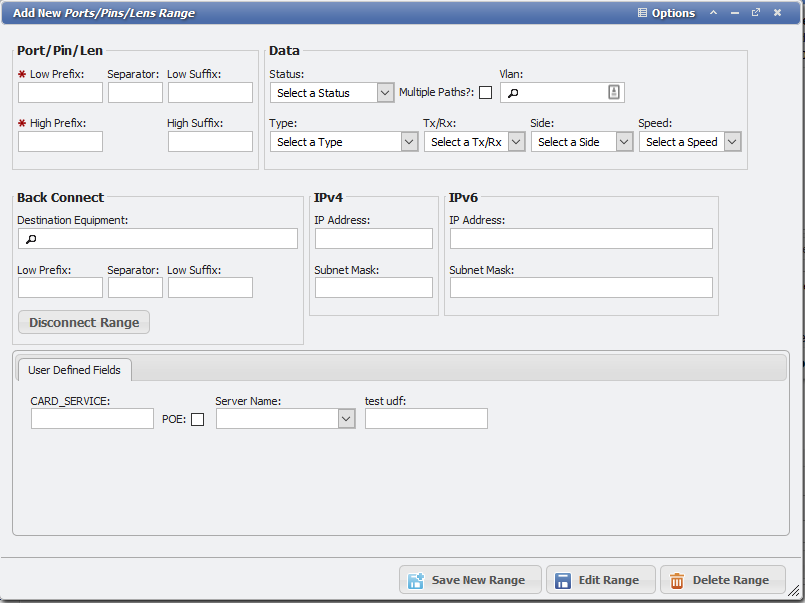
Add New Ports/Pins/Lens Form example
There are three Required fields on the Ports/Pins/Lens form, the 'Port/Pin/Len' field, the 'Status' field and the 'Side' field.
Valid statuses that can be set are: 'Left In', 'Spare', 'Assigned', 'Reserved', 'PDPC', 'Pending Disconnect', 'Pending Connect', 'Bad', and 'Unknown'. More information about what the intended usage of the various statuses can be found on the PPL and Pair Status page.
Parent Equipment
The 'Parent Equipment' field displays the 'Equipment ID' from the Port/Pin/Len's Parent Equipment. This field is read-only, but by clicking on the
Port Alias
Users can specify a 'Port Alias' for a given PPL. The Port Alias will override the PPL field on Grids and Reports to display the Port Alias. This is useful when a unique field is needed in the Port/Pin/Len field to specify the PPL record when interfacing with external systems. The Port Alias will only display internally and makes it easier to identify the PPL record without having to memorize the unique value that is stored in the PPL field.
For this example, the Port/Pin/Len field is set to "Unique PPL" and the Port Alias field is set to "Generic Alias".
When the User selects the Ports/Pins/Lens tab on the Equipment record that the Port/Pin/Len is attached to, the Users will only see the Port Alias value. The unique value in the Port/Pin/Len field will not display so long as there is a Port Alias value.
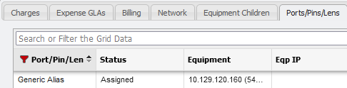
Alias example on PPL Grid
Picker behavior
It is important to note that the Picker behavior will also be overridden by the Port Alias field.
For example, if the User searches for "Generic Alias" in the Origination Port/Pin/Len Picker on the Path Leg form then the PPL will be found and values will populate like normal.
Origination section of Ports/Pins/Lens Form
However, if the User were to search for the "Unique PPL" in the Origination Port/Pin/Len Picker, no value will be found as a match. The "Unique PPL" value will only be used for connections with external systems.
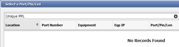
Select a PPL form example
View Path behavior
This overriding behavior will carry through to the View Path Report and display the Port Alias there as well. In this example, the
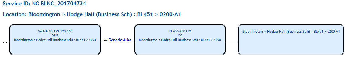
View Path example
Other Fields
The 
The User can also designate the following:
Type: This is the type of the Port the PPL is in the record. The values in this list come from the List Values of the Type: PORT_TYPE.
Tx/Rx: Shorthand for Transmit/Receive, denotes if the Port transmits, receives data, or if it both transmits and receives. The values in this list come from the List Values of the Type: PORT_TX_RX.
Side: Designates if the Port is on the Front, Back, or Cross-Connected on the Equipment. The values in this list come from the List Values of the Type: PORT_SIDE.
Speed: How fast the Port transmits data. The values in this list come from the List Values of the Type: PORT_SPEED.
IP Address
From the Ports/Pins/Lens form, the User can assign IP Addresses to the PPL in either 'IPv4 Address' or 'IPv6 Address' formats.
IP Address fields example
Back Connect
Users can specify that a Port/Pin/Len is set to 'Back Connect'. Back Connect is a method to connect two pieces of Equipment together, without having the connection appear in the Cable Path. This is useful for connecting two pieces of Equipment like a Switch to a Patch Panel. When a User attempts to disconnect the Cable Path this Back Connect will remain in place. When ports are transferred, any Back Connects are transferred along with the port.
Back Connect fields example
In the Back Connect section, there are two fields; the 'Destination Equipment' and the 'Destination Port/Pin/Len' pickers. Neither field are Required until the other picker has a value.
Setting Back Connection
To set a Port/Pin/Len (PPL) to 'Back Connect' follow these steps:
Open the Equipment record that should have a Back Connection set up. In this example, a Switch with an Equipment ID of "Test Switch One" is used.

Equipment ID Test Switch One example
In the Destination Equipment picker the Patch Panel "Test Patch Panel One" is selected.
This makes the Destination Port/Pin/Len picker Required.

Destination Port/Pin/Len field example
Click on the Destination Port/Pin/Len Picker and select a PPL.

Destination PPL field with PPL selected example
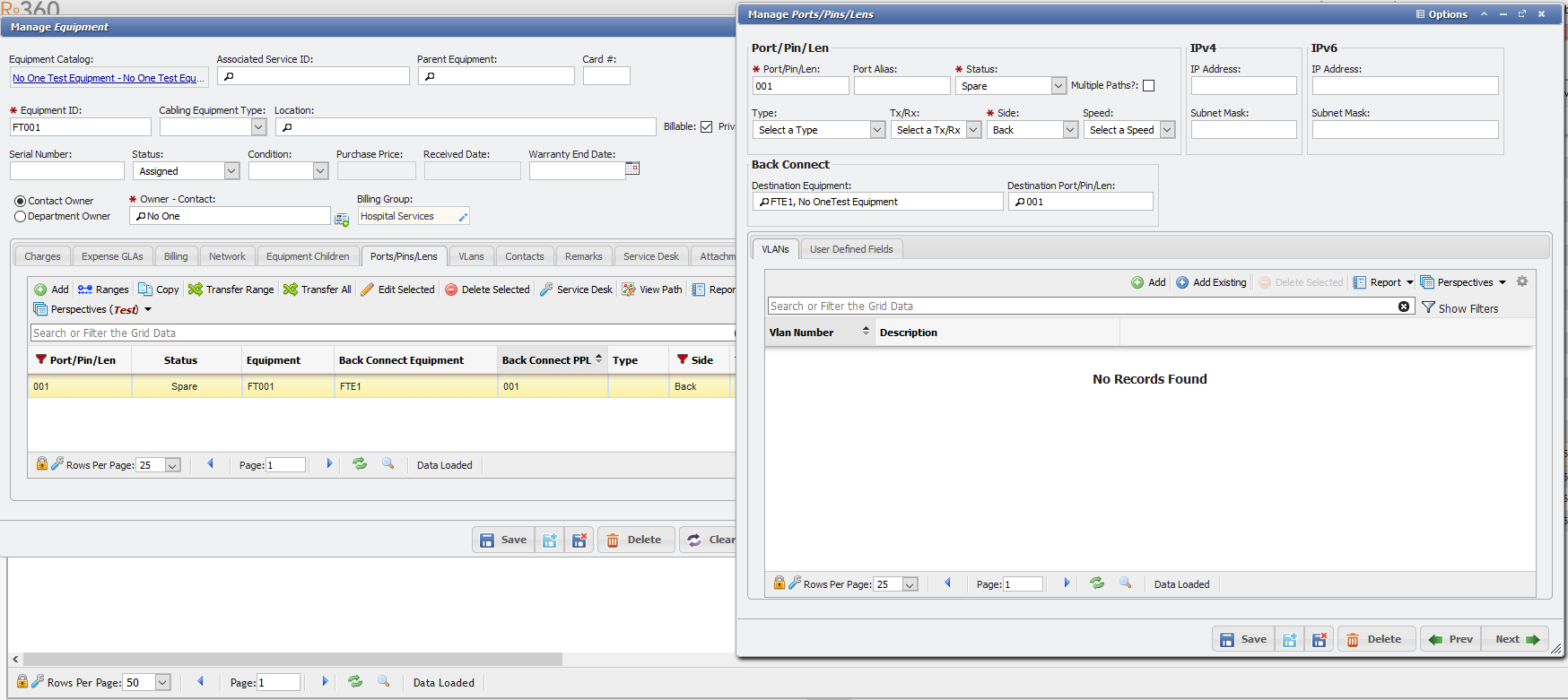
A User could instead select the Destination Port/Pin/Len record and have the Destination Equipment picker automatically fill in.

Manage PPL form with Back Connect example
Save the PPL record.

PPL record on Test Switch One example
The Switch "Test Switch One" will now reflect the Back Connection in the Ports/Pins/Lens tab of the saved PPL record.
The Port/Pin/Len (PPL) records for both pieces of Equipment reflect the 'Back Connection'.
On the PPL tab of the Patch Panel "Test Patch One" in the grid.

Test Patch Panel One on PPL tab example
Also on the opened PPL record.

Manage PPL form with Back Connect example
The two pieces of Equipment are now linked with a Back Connection.
Remove a Back Connection
Back Connects prevent deleting a PPL because both pieces of Equipment need that Back Connect reference. In order to Delete a PPL, clear the Back Connect Equipment from the PPL form for one of the two pieces of Equipment. This will remove the Back Connection, allow the User to delete the PPL, create a new one, and then apply the Back Connection to it instead. When you remove a back connect from one PPL it will remove the Back Connect from both PPLs.
Remove Single Back Connect Example
If there is a range of Back Connects to remove from a single piece of Equipment, it can be done using the

Remove Back Connect Range Example
Path Leg Usage
Linking Equipment with a Back Connection will only store on the relevant Equipment records and serves as a method to track the two link pieces of Equipment together. However, Path Legs can be easily generated to include these two pieces of Equipment in a Path. This can be done from the Service Desk or the Cable Paths form. If a User attempts to select a piece of Equipment with this Back Connect set up, the other piece of Equipment will automatically pull into the relevant fields of the Ports/Pins/Lens form.
To quickly create a Path Leg with Back Connected Equipment follow these steps:
Begin a new Path.
Either by clicking the
button on the Service Desk > Cable tab.
Or by clicking the
 button on the Cable Paths form.
Both methods will open the 'Add New Path Legs' form.
Add New Path Legs form example
In the 'Origination Equipment' Picker select the Switch "Test Switch One":

Add new Path Leg example
Note that since an Origination PPL is not yet selected only the fields relevant to the Origination Equipment are filled in.
Now in the Origination Port/Pin/Len picker select the Port '1' which was set as a Back Connected piece of Equipment previously.

Add new path leg example
Note that the entire set of fields for the Destination autofill with the data for Patch Panel "Test Patch Panel One" because of the Back Connection.
At this point if a User wants to edit data in the Destination, that data could be edited to create a different Path Leg. There is no enforced link between the Back Connected Equipment and what exists on the Path Leg. The autofill is for convenience only.
Click the

Add new Path leg example
For this example, a Jack is also selected for Path Leg 200.

Manage Path leg example
Close the Add New Path Legs form.
From the Service Desk > Cable tab click the
From the Cable Paths form click the
The View Path should look something like this:
Back Connect Path Leg Deletion
Even though Back Connect Equipment can help to create a Path Leg, the two Back Connected Equipment records will maintain their respective associations even if the Path Leg is deleted.
Select Path Leg #100 and click the Delete Selected button.

Manage Path form example
Click the

View Path leg 200 example
In the View Path report the Patch Panel "Test Patch Panel One" is still the first part of the Cable Path.

VIew Path example
Note that even though the Patch Panel is Back Connected to the Switch "Test Switch One" that connection does NOT show in the Path Leg, unless it is specifically selected as in the previous example.
With the Path Leg still deleted the User can confirm the Equipment records still have their respective Back Connect pickers having set values.

Manage PPL form example
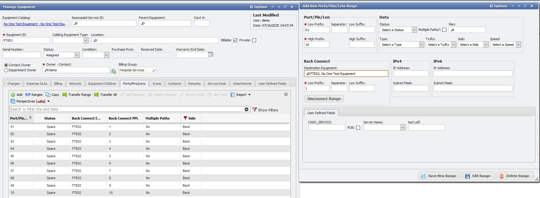
Back Connect Ranges
The PPL Range form allows for Back-Connect Ranges. Below is the add new "Ranges" form from the Port/Pins/Lens grid on any Cabling Equipment. To use this feature, the user just needs to enter the Destination Equipment and designate a low prefix to a low suffix range to be added. This functionality allows the User to quickly connect multiple pieces of Equipment together, without having the connection appear in the Cable Path.
Add new, ports, pins, lens range form
VLANs
An additional feature of the Ports/Pins/Lens form is the ability to add a VLAN if one does not yet exist on the VLANs tab.